Design of Specimen
The design of the frame is based on a number of design standards, including the 2000 International Building Code, the 1997 AISC Seismic Provisions, the ACI 318-99 code, and the 1994 ASCE Joint Recommendations. The design of the beams were predominantly controlled by the strength requirement while the size of the columns were controlled by strong-column weak-beam. In order to meet drift requirements in the frame, the beam sizes were increased by about 10%. Note that the design of this frame is meant to push the limits of the code and therefore is not conservative. In fact, the SCWB ratio is not met for some of the joints in the frame. The final member sizes as well as measured material properties are shown in the table below.
|
Floor |
Steel Beam |
Floor |
RC Column |
|
|||||||||
|
Section (mm) (1) |
Material (2) |
fy(Mpa) (3) |
fu(Mpa) (4) |
Section (mm) (5) |
fc¡¦ (MPa) (6) |
Rein. bar (7) |
Fy (MPa) (8) |
Fu (MPa) (9) |
|
||||
|
1st |
H600x200x11x7 |
flange |
A572 Gr.50 |
402 |
525 |
1st |
650x650 |
1C1 |
50.5 |
8-#11 |
529 |
699 |
|
|
1C2¡B1C3 |
45.8 |
12-#11 |
|
||||||||||
|
web |
410 |
507 |
|
||||||||||
|
1C4 |
44.3 |
8-#11 |
|
||||||||||
|
2nd |
H500x200x10x16 |
flange |
A572 Gr.50 |
484 |
635 |
2nd |
650x650 |
2C1 |
44.2 |
4-#11 |
529 |
699 |
|
|
2C2¡B2C3 |
44.8 |
12-#11 |
|
||||||||||
|
web |
517 |
642 |
|
||||||||||
|
2C4 |
45.2 |
4-#11 |
|
||||||||||
|
3rd |
H396x199x7x11 |
flange |
A572 Gr.50 |
388 |
526 |
3rd |
650x650 |
3C1 |
45.4 |
4-#11 |
529 |
699 |
|
|
3C2¡B3C3 |
44.8 |
12-#11 |
|
||||||||||
|
web |
430 |
535 |
|
||||||||||
|
3C4 |
46.9 |
4-#11 |
|
||||||||||
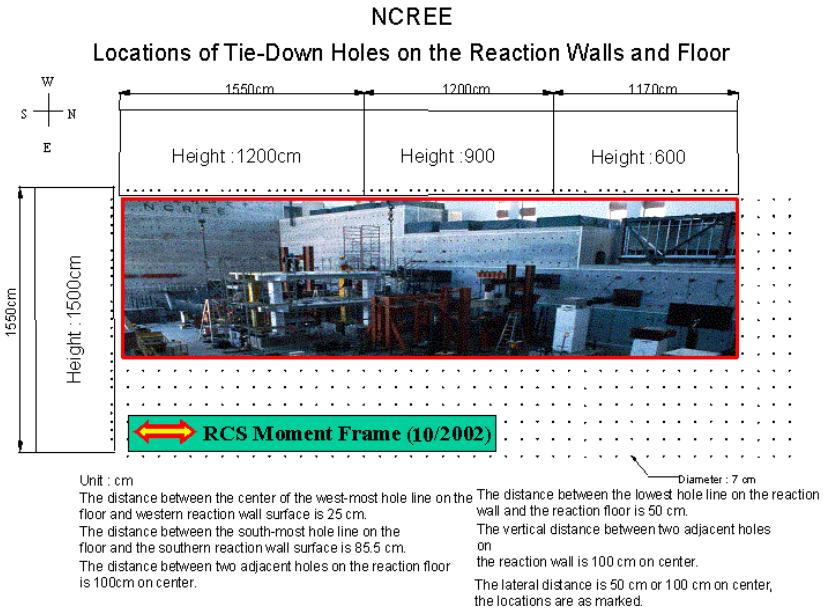
The theoretical plan view of the structure is shown below along with the actual elevation view in the laboratory.
This is a precast system that utilizes grouted column splices that are located 1-meter from the bottom of the column at the first floor and at the slab level at the second and third floors. The beams are spliced at 1500mm from the centerline of the column.
Seismic Design Criteria
•IBC 2000
¡VDesign Hazard (SDS = 1 g; 10% in 50 year)
¡VR = 8 (Composite Special Moment Frame)
¡VDrift: Dd*Cd < 0.02
¡VEccentricity 5% in plan (7.5% increase in design shear)
¡VPeriod: 1.2Ta = 0.6 sec
•Design Base Shear
V/W = (SDS /R)*1.075 = 0.134 ( = 260 kips = 1156 kN)
Drift requirement increases this to an effective base shear of about 10% to 0.147
•Beams
¡VSized for strength based on negative bending strength (steel beam)
¡VIncreased by about 10% to satisfy drift
•Columns
¡VSized for SCWB criteria
•Composite Joints
¡VChecked for SJWB criteria
•Bolted Moment Connections
¡VDesign strength to develop 1.1RyMp,steel at column face